

 English
  中文简体
中文简体  русский
  Español
  عربى
عربى 
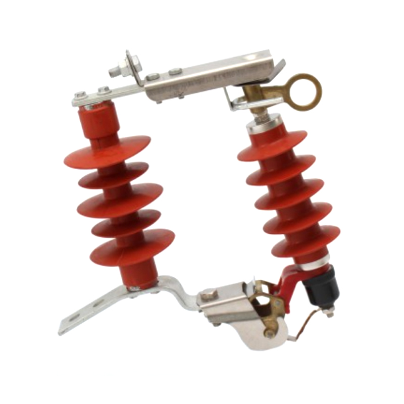
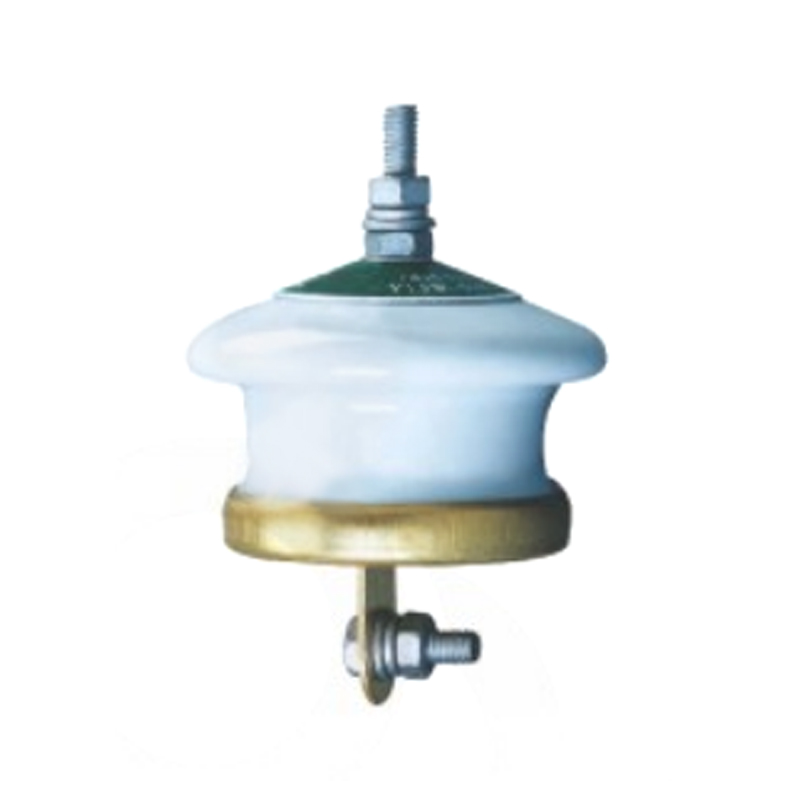
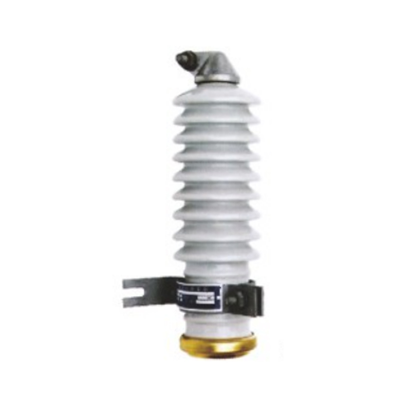
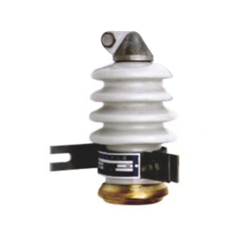
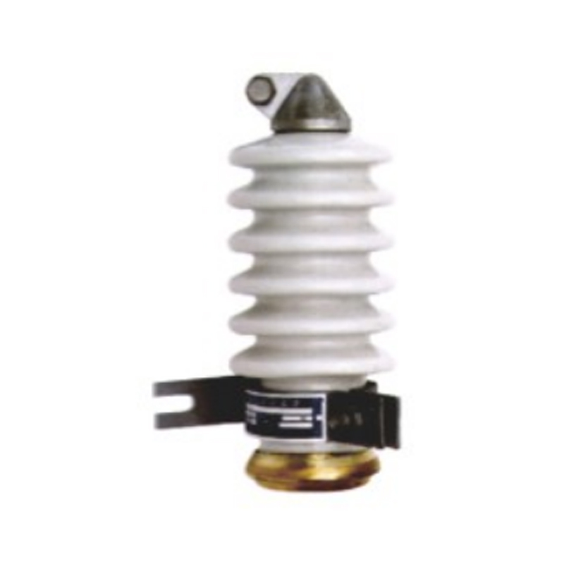
Fall Arrester
The HY5WS-17/50DL-TB drop-type lightning arrester is a modified distribution zinc oxide arrester cleverly integrate...
The KYN28-12(GZS1) Removable AC Metal-clad Switchgear (hereinafter referred to as "switchgear'”) is suitable for three-phase AC50Hz power system. it is used for receiving and distributing electrical energy and controling, protecting, and monitoring circuitsThe newly introduced high-current, high-breaking switchgear can also be used independently for high-voltage generator outlets.This product complies with the standards: GB3906 "3~35kV AC Metal-Enclosed Switchgear”lEC60694&GBT11022 "CommonTechnical Requirements for High Voltage Switchgear and Control Equipment Standards," lEC62271-200 "AC Metal-EnclosedSwitchgear and Control Equipment with Rated Voltages Above 1 kV up to and including 52 kV."
Ambient Air Temperature: Maximum temperature +40°C, Minimum temperature-15C Humidity Conditions: Daily average relative humidity:≤95% Daily average water vapor pressure does not exceed 2.2kPa Monthly average relative humidity: s90% Monthly average water vapor pressure does not exceed 1.8kPa Altitude: 2500m and below
Seismic Intensity: Not exceeding 8 degrees
The ambient air should not be subject to corrosive or flammable gases, steam, or other obvious pollution. No places with constant severe vibrations. If used beyond the normal conditions specified in GB3906, it should be negotiated between the user and the manufacturer.
| Item | Unit | Data | ||||
| Rated Voltage | KV | 3.6, 7.2, 12 | ||||
| Rated Frequency | Hz | 50 | ||||
| Circuit Breaker Rated Current | A | 630, 1250, 1600, 2000, 2500, 3150, 4000 | ||||
| Switchgear Rated Current | A | 630, 1250, 1600, 2000, 2500, 3150, 4000 | ||||
| Rated Short-Time Withstand Current (4s) | KA | 16, 20, 25, 31.5, 40, 50 | ||||
| Rated Peak Withstand Current (Peak) | KA | 40, 50, 63, 80, 100, 125 | ||||
| Rated Short-Circuit Breaking Current | KA | 16, 20, 25, 31.5, 40, 50 | ||||
| Rated Short-Circuit Making Current (Peak) | KA | 40, 50, 63, 80, 100, 125 | ||||
| Rated Insulation Level | 1min Power Frequency Withstand Voltage | Between poles, poles to the ground | KV | 24, 32, 42 | ||
| Between fractures | KV | 24, 32, 48 | ||||
| Lightning Impulse Withstand Voltage (Peak) | Between the poles, squeezing the ground | KV | 40, 60, 75 | |||
| Between fractures | KV | 46, 70, 85 | ||||
| Protection Level | The shell is IP4X, and when the doors between compartments and circuit breakers are open, it is IP2X | |||||
Note: 1. The short-circuit capacity of current transformers should be considered separately.
2. Technical parameters for ZN63A-12 can be found in the corresponding sample.
3. For altitudes of 1000m, rated current should be s1250A, and rated short-circuit breaking current should be s31.5kA.
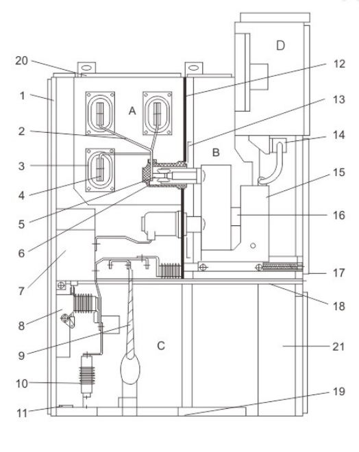
A.Bus compartment
B.Circuit breaker handcart compartment
C.Cable compartment
D.Metering compartment
1.Shell
2.Branch busbar
3.Busbar bushing
4.Main busbar
5.Static contact device
6.Contact box
7.Current transformers
8.Earthing switch
9.Cable
10.Lightning arrester
11.Earthing busbar
12.Loading and unloading partition
13.Partition(valve)
14.Secondary plug
15.Circuit breaker handcart
16.Heating device
17.Detachable horizontal partition
18.Earthing switch operating mechanism
19.Bottom plate
20.Pressure relief device
21.Control wire trough Schematic diagram of switchgear structure


Photovoltaic Module Manufacturer

