

 English
  中文简体
中文简体  русский
  Español
  عربى
عربى 
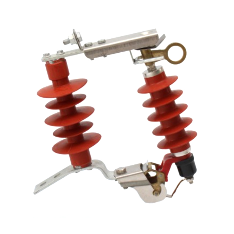
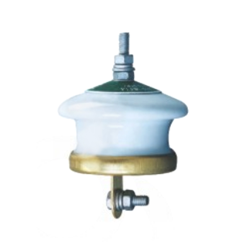
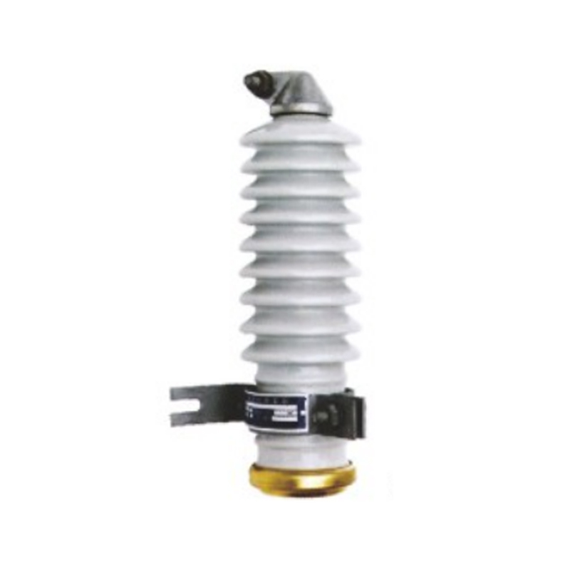
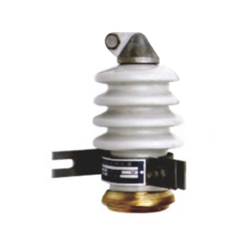
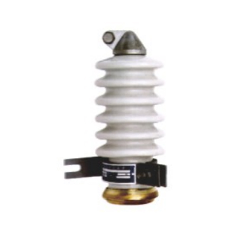
Fall Arrester
The HY5WS-17/50DL-TB drop-type lightning arrester is a modified distribution zinc oxide arrester cleverly integrate...
HXGN囗 -40,5 is a Prefabricated fixed Ac metal-clad switchgear designed in accordance with GB3906-91 "3-35kV ACMetal-Enclosed Switchgear." its enclosure complies with the lP2X protection level specified in GB4208-92. Thisswitchgear is a complete set of indoor devices for three-phase AC 50Hz single bus and bus-side bypass systems, servingtoreceive and distribute 35KVnetwork electrical energy.
1. Main circuit scheme number, purpose, single-line system diagram, arrangement diagram, and layout diagram of the distribution room, etc.
2. Auxiliary circuit wiring diagram, terminal arrangement diagram.
3. Type, specifications, and quantity of electrical components inside the switchgear.
4. Requirements for control, measurement, and protection functions of the switchgear, as well as other requirements for interlocking and automatic devices.
5. If busbar bridging is required between switchgear or incoming cabinets, provide specific requirements such as rated current of the busbar bridge, span, height above ground, etc.
6. When accessories and spare parts are needed, specify the type and quantity.
7. When the switchgear is used in special environmental conditions, provide detailed information when ordering.
Altitude: Not exceeding 2500m.
Environmental Temperature: Upper limit +40℃, lower limit -5℃.
Relative Humidity: Daily average not exceeding 85% (+25℃).
Seismic Intensity: Places without severe vibration and tilting not exceeding 5 degrees.
Environmental Conditions: Places without explosion danger.
Note: When exceeding the above normal operating conditions, users can consult with the manufacturer to determine.
| No. | Item | Unit | Data | |
| 1 | Rated Voltage | KV | 40.5 | |
| 2 | Maximum Rated Current | A | 2000 | |
| 3 | Rated Breaking Current | KA | 25 | 31.5 |
| 4 | Rated Closing Current (Peak) | KA | 63 | 80 |
| 5 | Limit Passing Current Peak | KA | 63 | 80 |
| 6 | Rated Short-time Withstand Current (4s) | KA | 25 | 21.5 |
| 7 | Standard Dimensions (Width×Depth×Height) | MM | 1918×3250×3125 | |
| 8 | Protection Level | IP2X | ||
| 9 | Weight | KG | Approximately 1500 | |
HXGNO-40.5 fixed-type AC metal-clad switchgear is a fixed structure, and its basic frame is made of shaped steel and steel plates bent and welded. The cabinet shell has an IP2X protection level. This switchgear is mainly assembled from the frontl cabinet and the rear cabinet, and different functional units are set for different purposes. The live bodies in the cabinet arel mainly insulated with air, and the insulation distance between each live body and the ground is not less than 300mm.

The structure of the switch cabinet is shown in the figure
1. Circuit breaker, small busbar, and terminal chamber
2. Main busbar disconnector
3. Current Transformer4. Current Transformer
5. Bypass bus disconnector
6. Line disconnector
7. Bypass busbar room
8. Usage card
9. Left control panel
10. Lower left door
11. Simulated busbar sign
12. Nameplate
13. Vacuum circuit breaker
14. R-C type overcurrent absorber (variable element)
Installation base reference diagram


Figure 2 Schematic diagram of single row flat layout of switchgear, buried foundation channel steel, and position of primary cable trench foundation and secondary control cable Notes: The ruler in parentheses is used for small attached cabinets.


Photovoltaic Module Manufacturer

